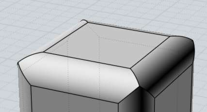
Here is an example of a large area with shallow curvature that didn't get many polygons. By default it will be applied only to curved surfaces leaving planar surfaces unaffected, but this can be changed to only apply to planar surfaces for special meshing needs, or to apply to all surfaces. You can also adjust the drop-down to limit additional subdivisions to a specific type of surface. Areas that have shallow curvature will tend to get fewer polygons in them because the regular density control that is adjusted by the slider is based only on curvature and not lengths. This can be used to add detail to larger areas that have shallow curvature. You can enter a distance here which will force polygons that are larger than this length to be broken down into smaller pieces. The "Divide larger than" option provides another way to refine the mesh in certain areas. For example, if you want a very low polygon mesh you may want to type in a larger angle here than the slider normally permits. This option just allows you to control it more directly and to allow for values outside of the normal slider range. This is the same value that is controlled by the slider. When the maximum angle is larger, fewer subdivisions will be forced in curved areas and coarser polygons will be allowed. When the maximum allowed angle is small, it will force additional subdivisions along more tightly curved areas. The Angle option controls the maximum angle allowed between the surface normals at the corners of each polygon. Turning welding off may also help separate polygons out into different chunks for each original surface during later polygon editing. Unwelded edges will get an accent line in a sketch rendering. Also, sometimes you may want to have points unwelded for certain special effects, such as doing a sketch or toon style rendering. Typically welding is left on for normal rendering use but some programs may have difficulties with welded meshes.

The points are stacked on top of each other, shown slightly separated here for illustration: The vertices are shared between polygons:Įxample of unwelded polygons - in this case each polygon across the unwelded edge has its own individual vertices. When welding is off, the polygons on each side of the edge will have their own individual points which are stacked up in the same location.Įxample of welded polygons - each polygon from either side of a joined edge will be hooked into the same vertex. When welding is on, polygons will share a single point in common along the shared edge. Welding controls how polygons are connected to points along shared edges between surfaces. You can click on the arrow in the lower-left corner of the compact dialog to expand it to show more options: Some polygon file formats don't allow N-gons, for example STL or 3DS files can only contain triangles, so you won't see this option when exporting to these formats. If you see bad results when importing N-gons into your polygon application, try reducing this option to Quads & Triangles, or Triangles only. Some programs have difficulty dealing with complex N-gon shapes. The Output: option controls the type of polygon data that will be created, whether to allow creation of N-gons (polygons with more than 3 or 4 sides), or whether to break polygons up to only allow 3 or 4 sided polygons.

A denser mesh will be smoother visually but will also contain a lot more data. Move the slider to the right to create a denser mesh with more polygons in it. This will reduce the amount of data generated but will also give a more jagged appearance to the mesh.

Move the slider to the left to create a lighter mesh with fewer polygons. Initially the dialog is shown in its compact form: So you'll generally want to make sure surfaces that are next to one another have been joined together into one connected solid object before exporting mesh data.

MoI does extra work to align mesh vertices along shared edges between joined surfaces. The "Meshing options" dialog is shown during this process to control different aspects of how the polygon data is generated.ĭuring the meshing process the number of generated polygons and points are displayed in the upper-right corner of the main window where command options normally are shown. When saving to a polygon file format, MoI needs to convert from smooth surface data into faceted polygon data.


 0 kommentar(er)
